Reverse flow is a possibility that always has to be considered when building a process system. Over more than 13 years working in R&D with lab- and pilot-scale reactor systems, both as a researcher designing and building the units and later as a process safety engineer reviewing them, the approach was almost always the same: any time we did not want something to flow backward, we installed a check valve.
Where the site headers dropped to a unit, every gas, including hydrogen, nitrogen, and hydrocarbons, got a check valve before it reached the process equipment. That was written down and applied to every unit we built. Downstream of every mass flow controller, a check valve. On any line with an open purge to atmosphere, a check valve. On the line to the waste can, a check valve so nothing could back up into the system. And wherever two process streams met, a check valve on the one that should not go the other way.
Some of those were written standards and some were habit, but the effect was the same. A pilot unit ended up with a dozen or more identical valves, same part number, same P&ID symbol, and nobody thought about any of them again. In HAZOPs, which I led, the reverse flow guide word came up hundreds of times. The answer was almost always “there’s a check valve,” and we moved on. What we never asked was the question that actually matters: is that valve a process device or a safety device? Those are different responsibilities, but we often manage the valves the same way.
Scope: This article is about the small spring-loaded poppet check valves common on lab, bench, and pilot-scale systems, including the 1/8 to 1 inch tube-fitting and NPT valves from Swagelok, Parker, and similar suppliers. These valves commonly use an elastomer O-ring or bonded poppet. Larger process plants also use swing, dual-plate, piston, and nozzle check valves with metal seats, and those can fail differently. The general principle here carries over. The specific numbers and failure modes do not.
Classifying Check Valves by Function
Go back through that list and ask what each valve is actually protecting.
The one downstream of the mass flow controller may be protecting the controller. If reverse flow only fouls or damages the instrument, with no hazardous consequence, that is a process function. If the damage can lead to a hazardous release or loss of control, there is a safety function to evaluate too.
The one on the waste line is keeping waste from backing into the unit. If the only consequence is a cleanup, that is a process function. If the waste can react with the contents of the unit or cause a hazardous release, there is a safety function. The consequence decides.
The one on the open purge may be keeping air out of a line that carries hydrogen. If air ingress can create a hazardous mixture and the check valve is being relied on to prevent it, that is a safety function.
The one at the header drop is the interesting one. Its reverse-flow function is to protect the shared supply from whatever your unit might push back. Whether that material reaches another system depends on the connections, pressures, and operating conditions. On a shared branch, you may not even know every user or where the material could go. That uncertainty makes the consequence harder to establish. It does not establish that the consequence is harmless.
There is another way to make the classification. At our site, fire suppression systems and lab hoods were treated as safety-critical by default. Their basic status did not have to be established again for whatever happened to be in the lab that day. A site could take the same approach to check valves protecting shared gas headers and branches: designate them as safety-critical by standard, with a defined purpose of preventing process material from entering the shared supply. The team would not have to prove that contamination will reach a particular neighboring experiment before giving the valve a tag and a maintenance schedule.
That would be a deliberate site requirement, with an owner and a maintenance basis. A standard that only says where to install a check valve leaves that work unfinished. The standard should also define the services and connections it covers, and the protection the valves are expected to provide.
A check valve can serve a process function, a safety function, or both. Keeping a feed line primed or protecting an instrument may be purely operational in one system and safety-critical in another. The distinction comes from the consequences and the protection being relied on, or from a site standard that deliberately assigns that safety responsibility.
Many of the safety-critical ones I encountered started life as ordinary process devices without anyone explicitly deciding they should serve as safeguards. During normal operation the pressure relationship holds, upstream higher than downstream, and the valve does nothing. Then there is a transient. You refill a feed vessel and its pressure drops. You swap a cylinder and expose the line to a different supply pressure. You switch gases on a manifold. You depressurize one side for a sample or a filter change. You shut down and one system bleeds off faster than the other. For a few minutes the pressure relationship inverts, and in that window the check valve is no longer just a convenience. It is being relied on as a barrier.
When the valve is being relied on to prevent a hazardous mixing or reverse-flow scenario, it has a safety function whether or not the P&ID or equipment list calls it that. Identifying a check valve as safety-critical tells us what we are relying on it to do. It does not establish that the valve can do it under the conditions that create the demand. That still requires a suitable valve, a defined performance requirement, and a way to verify it.
Case Study: Reverse Flow Into a Shared Helium Header
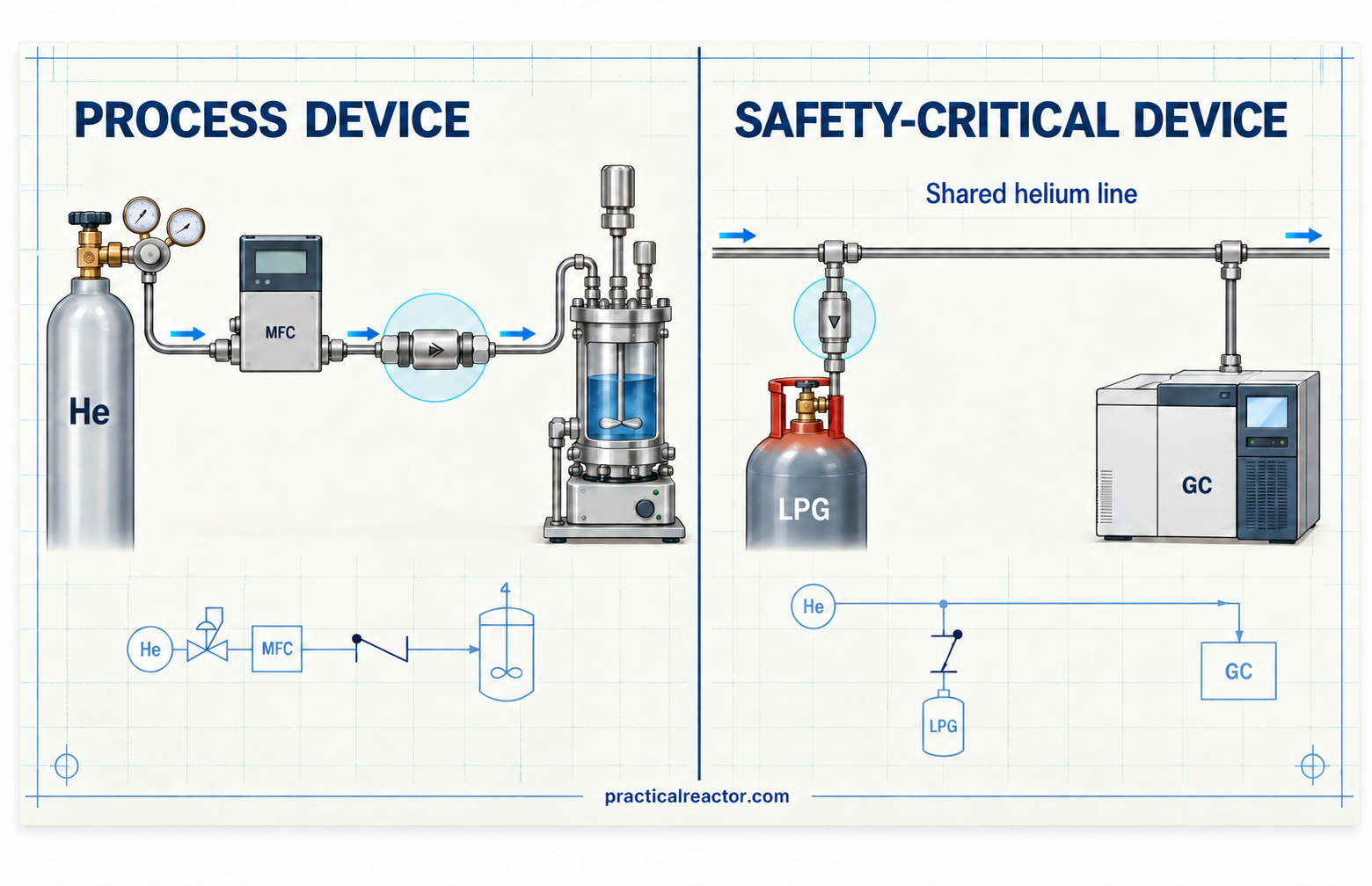
The incident that sticks with me happened in a lab I worked in. An LPG cylinder sat under a helium blanket. Upstream of where the helium tied into the cylinder there was a branch: one leg went to the cylinder, through a check valve, and the other leg went to a gas chromatograph on a neighboring process, where the same helium was the carrier gas.
One day the person running the GC saw something in their data that should not have been there. Troubleshooting worked backward from the instrument and ended at the branch. LPG had reverse-flowed out of the cylinder, through the check valve, up into the helium branch, and into the carrier gas line of a GC on a different process.
Nobody had done anything wrong in the sense of violating a procedure. Two ordinary things happened at once. A fresh LPG cylinder had been installed. At the same time, the helium supply pressure feeding both the cylinder blanket and the GC had drifted low. I do not recall whether the cause was a regulator adjustment or the supply pressure, but the effect was the same. The pressure relationship reversed, allowing LPG to move backward through the valve, while the reverse differential may still have been too small to establish a tight seal.
Whether the check valve failed was never fully determined. I no longer have the valve model, cracking-pressure specification, or inspection results, so I cannot say whether it was damaged, contaminated, worn, or simply operating within its published reseal characteristics. What I understood later, once I read the catalog more carefully, was that a mechanical failure was not the only possible explanation. Depending on the valve and spring, it may not have seen enough back pressure to reach the manufacturer’s defined reseal condition.
Look at what that valve was. It was on a helium line, a utility, and it looked like a routine process device on the P&ID. Its actual purpose was to keep material from going back into a shared helium line. The day the cylinder changed and the helium pressure sagged, it became the only barrier between LPG and an analytical instrument on an unrelated process. Nothing in the design documentation identified that function or showed that the valve had been selected for the differential pressure it might experience during that transient.
Nothing in our maintenance system would ever have found it on purpose. The relief valves on that system had tags, intervals, and pop-test records. The vapor monitors had calibration schedules. The check valve had a purchase order and nothing since. The reason we found it at all is that a GC is a very sensitive reverse-flow detector, and somebody happened to be looking at one.
Cracking Pressure, Reseal Pressure, and Seat Leakage
Page 4 of the Swagelok catalog MS-01-176, Rev. N, illustrates why the helium-line explanation is plausible. This is an example of a possible mechanism, not an identification of the valve or the cause of that incident. For a C series valve with a nominal 1/3 psi spring, reseal pressure is listed as “up to 20 psi back pressure.” Reseal is defined as the pressure at which there is no indication of flow. In other words, the catalog does not guarantee that the valve will reach its defined no-flow condition at a small reverse differential. Depending on the individual valve, substantially more back pressure may be required to establish a tight seal. The 1 psi spring is listed as requiring up to 12 psi of back pressure. The 10 and 25 psi springs are specified to reseal while forward inlet pressure is still present.
These figures are specific to the cited revision and valve series; selection should use the specifications applicable to the actual valve.
The same catalog notes that a valve not actuated for a period of time may have a higher initial cracking pressure. That is a separate forward-flow concern, not an explanation for reverse leakage. It means a valve that sits still most of its life may require more pressure than expected when it is finally asked to open.
There is also a factory seat-leakage allowance. The catalog states a maximum allowable leak rate of 1 standard cm³/min of nitrogen. If a valve leaked continuously at that maximum rate, it would amount to roughly 526 standard liters, or 18.6 standard cubic feet, per year. Actual leakage in service will depend on the fluid, pressure differential, temperature, and condition of the seat, so this is not a prediction of annual process leakage. It does show that “closed” and “zero flow” are not automatically the same thing.
That leaves at least two ways one of these valves can pass reverse flow without a broken spring or a visibly damaged part. It may not yet have reached its defined reseal condition, or the seat may be leaking within its allowable test limit. Both conditions are invisible unless somebody looks, and nobody looks if nobody has identified the valve as safety-critical.
Industry Guidance for Safety-Critical Check Valves
I had this conversation more than once, both in the lab and later as the site process safety engineer. The need was easy to argue. Finding precedent that clearly applied to our small spring-loaded valves was harder. Our design standards said where to put check valves and said nothing about maintaining them, and when I asked around, most people I spoke with did not have a maintenance schedule for this type of check valve either. They sat in the gap between process equipment and safety equipment.
API 570 recognizes critical check valves and provides a precedent for including them in an inspection or testing program. It addresses in-service piping in the petroleum and chemical process industries; it does not automatically govern a bench or pilot system merely because the facility is covered by PSM. The useful principle here is to identify which valves are vital to process safety and give them a documented inspection or testing basis.
Crediting a check valve as an independent protection layer in a LOPA requires a further evaluation. Published CCPS guidance and Olsen’s discussion of check-valve reliability make clear that credit depends on specified conditions and a justified maintenance and testing basis. A generic failure probability does not establish the suitability of a particular valve for a particular service. The amount of reverse leakage the process can tolerate matters too. The credit and the test basis come as a pair, and you do not get to take one without the other.
At lab and pilot scale, the first step is to identify which valves have safety responsibilities, either through scenario review or a site standard. Those valves need documented performance requirements and a program to maintain and verify them.
Evaluating Check Valves During a HAZOP
Three questions, in order, every time the reverse flow guide word comes up and someone points at a check valve. Ask them about the valves the design standard put there too. A header-drop valve can disappear from the discussion precisely because it is standard.
What is the transient that creates the demand? Review startup, shutdown, depressurization, maintenance, cylinder changes, loss of utilities, gas switching, and other credible operating modes. Identify when the pressure relationship could reverse and what could happen if the valve passed reverse flow. That consequence determines whether the scenario creates a safety function. Also check whether a site standard already designates the valve as safety-critical. For a shared supply, document what is known about the connected users and what remains uncertain. An incomplete picture of the other users is not a sufficient basis to remove that designation.
Is it the only barrier? Identify every component or action that could prevent reverse flow, but do not assume each one is an independent protection layer. Confirm that a regulator is designed to withstand or prevent reverse flow. Evaluate whether procedural isolation is reliable for the specific scenario. If there are multiple check valves, consider whether they share the same design, service conditions, contamination exposure, or other common failure mechanisms. A second check valve may improve the design without qualifying as a second independent layer.
Now what do we do about it? A safety-critical check valve needs the same basic management controls applied to other safeguards: a unique tag, an assigned owner, a documented maintenance and inspection or testing schedule, an acceptance criterion, and records of the results. Those controls apply whether the designation comes from a specific hazard scenario or a site standard. Depending on the service, that may mean periodic replacement, inspection and rebuilding, or a reverse-pressure leak test performed under defined conditions. The acceptance criterion should be based on the valve specification and the amount of reverse leakage the protected system can safely tolerate. The manufacturer’s factory leak limit can be a useful reference, but it is not automatically the correct field acceptance criterion for every service. Forward flow through the valve every day does not demonstrate that it will stop reverse flow. A test of that safety function needs to challenge the valve in the reverse direction under conditions relevant to the demand, including the differential pressure at which protection is needed. Another option is to redesign the system to eliminate the credible reverse-flow scenario. Any resulting change in the valve’s safety designation should be documented and reconciled with the site standard.
The first step is to ask what happens if each check valve passes reverse flow, and what protection the site has committed to provide. Where a hazardous consequence or a site standard gives the valve a safety function, identify that function and establish how it will be verified. “There’s a check valve” is the start of that discussion.