
One control thermocouple tells you the temperature at one spot. Cold spots hide everywhere else, and they come from two different problems: gaps in coverage on plain tubing, and components that each need a different amount of heat. How to prevent the first and measure the second.
Why cold spots are expensive at startup
Cold spots have cost me days of troubleshooting twice, on two different units, from two different causes.
Vaporizing liquids is where uniform tracing matters most. If a section of line sits below the temperature the stream needs, vapor can condense there and revaporize later, so material reaches the GC unevenly. The control thermocouple reads setpoint while the problem sits somewhere it can’t see.
A cold spot also looks like every other startup problem. It shows up as inconsistent injections, the same symptom a bad flow controller, poor mixing, or a back pressure regulator or check valve making the flow sputter would give. The transfer lines, the valve box, and the column are all suspects too.
It matters most at startup because you don’t yet have a baseline. You haven’t seen this system’s data, so you don’t know what normal looks like, and you’re working through the kinks of the feed system at the same time. After a few clean runs you can compare against what the system should deliver. Before that, a heat-trace problem can pass for a design problem. It’s the same principle as in the GC baseline case study: find the test that eliminates a large part of the system quickly.
Two different problems
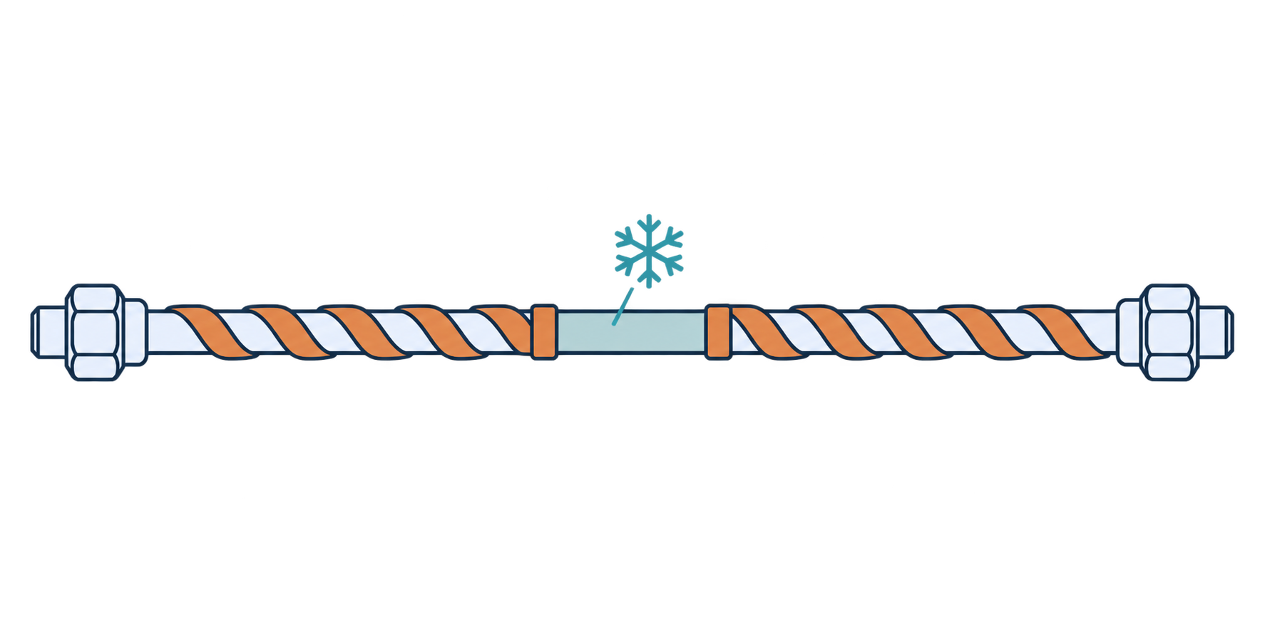
Plain tubing has no thermal-mass problem and no component rating to stay under. It just needs to be traced along its full length. When it isn’t, the fix is coverage, and there’s nothing to measure.
A line with several components is harder. Each valve, regulator, and cylinder has its own thermal mass, so it’s difficult to know how much heat each one needs to reach temperature without overshooting. That’s where measuring pays off.
A gap in the tape is a cold spot
Early in my career a heat tape failed on a reactor unit. I stripped the line, replaced the tape, and ran the new one down the length of it. When I got to the end, the tape stopped about two inches short of the end of the tubing. I decided that was close enough, since I’d insulate the stub really well.
The next day the unit heated up and the initial tests were fine. Once I started the reaction, the data was inconsistent. I spent over a day troubleshooting everything else, including the GC, then stopped the run. By the time I asked whether the tape I’d replaced could be the cause, I had lost about two days. I extended the tape to the end of the line, rewrapped, and the problem went away.
Stainless steel conducts heat poorly, and tubing has a thin wall and a small cross-section, so very little heat travels along the tube from the traced section into the stub. Two inches without direct heating can be a cold spot regardless of the process. What the process changes is whether that cold spot matters. On a stream with a large vapor fraction, it’s where material condenses.
Insulation slows heat loss, but it doesn’t add heat, and you can’t count on enough heat conducting in from the traced section.
There’s nothing to measure here. Take the tape all the way to the end of the line.
Components with different thermal mass
On a line with several components, coverage isn’t enough. A valve, a regulator, and a sample cylinder are different sizes, so the same tape heats them at different rates, and a single control thermocouple can’t tell you whether each one is reaching temperature or overshooting it.
When I first started building reactor systems, I spent a long time chasing inconsistent GC results on a newly built aromatics unit. I was feeding in a liquid standard of known composition, so the data should have been repeatable. It wasn’t.
I started where most people do, bumping the temperature of the transfer line because some spot was a little cold. It helped some, but I reached a point where I couldn’t raise it further without risking damage to something on the line. That’s the trap described in Where to Place the Control Thermocouple.
So I stripped the transfer line and rewrapped it. I found places where the tape contact was poor, and a couple of components whose thermal mass was likely too large for how I’d wrapped them. To confirm, I temporarily placed a thermocouple on each suspect spot, heated the line, cooled it, checked whether the spot reached temperature, and repeated.
The heating and cooling weren’t the slow part. The line heats in about 30 minutes and takes roughly twice that to cool, less if you pull insulation off to speed it up. The slow part was rewrapping the insulation and adjusting the heat tape each time. Without rushing, I could get two tests done in a day. Once every component was wrapped for its mass and reached temperature, the inconsistency went away.
The rest of this article is the faster way to do what I did on that unit.
The window, briefly
As covered in Where to Place the Control Thermocouple, every line has a floor the process needs and a ceiling set by the lowest-rated component, 148°C for a Swagelok 40G valve.
For a vaporized feed, the floor is the dew point of the stream at line pressure, not the boiling point of any one component at atmospheric pressure. The heaviest components usually set it, and higher line pressure raises it.
The setpoint sits at the floor plus a margin. That margin is a rule of thumb, 10 to 15°C. On a wide window you can live with it. On a tight one you want to know the real number.
Narrow the window with spare thermocouples
The ideal is a sensing point on every component. You may not have the I/O for that, but most labs have loose thermocouples sitting around. Put them on the components that matter and read them without connecting them to the control system.
There are two ways to read them:
- A handheld meter, such as a Fluke.
- A spare input on the PLC or a data logger, as long as it isn’t tied to a shutdown. Keep these readings monitoring-only. A thermocouple you installed for a survey hasn’t been validated as a safeguard.
The best habit is to leave them in place. I secure each junction to the component with fiberglass tape under the insulation, using a tape rated well above the line temperature. Glass cloth tape such as 3M 361 is listed to 450°F (232°C), against a 148°C valve ceiling. I leave the ends sticking out through the jacket and label each one.
The alternative is expensive. Each new position on a wrapped line means pulling back insulation, moving the thermocouple, rewrapping, and then waiting through another heat-up and cool-down. On the aromatics unit, that held me to two tests a day. With thermocouples left in place, one heat-up shows you every cold spot at once. You still have to rewrap to fix them, but you rewrap knowing where to look instead of testing one spot per cycle. When the data looks inconsistent, you can read the suspected cold spot before anyone touches the setpoint.
When you need it
You need this when one control thermocouple is serving several components that heat differently, such as multiple valves, or a valve plus a sample cylinder or regulator. You also want it on any new system where inconsistent data hasn’t been explained yet.
You can skip it when the section is uniform tubing with a single component, or when the window is wide enough that the standard 10 to 15°C margin is comfortable. With a 100°C floor and a 148°C ceiling, you probably don’t need it. With a 130°C floor, you probably do. Because leaving thermocouples in place is cheap, the bar on a borderline line is lower than it would be with a full unwrap per position.
Run the survey
- Choose the spots: the fastest-heating, lowest-rated component and the slowest or coolest one, plus any other component you have a doubt about.
- Secure each junction in firm contact with the component body, away from the heat tape, using fiberglass tape rated well above the line temperature. Label the leads.
- Before closing the insulation, warm each junction with your fingers and confirm the labeled channel rises. A reversed thermocouple will fall. A reading at ambient only proves the circuit isn’t open.
- Bring the line to setpoint, let it settle, and record each reading against the control reading.
A standard Type K thermocouple is good to about ±2.2°C, so two good ones can disagree by 4°C. That’s noise when you’re troubleshooting, but near a valve rating it comes out of your margin.
Set the setpoint from the survey
Each survey reading gives you an offset from the control reading. The coldest component’s offset is your floor penalty, and the hottest component’s offset is your ceiling penalty. The controller’s swing sits on top of both, so the setpoint has two limits:
- Setpoint ≥ floor + cold offset + half the control band
- Setpoint ≤ ceiling − hot offset − half the control band
If the controller holds setpoint ±2°C, the band is 4°C and half the band is 2°C.
For example, say the floor is 120°C, the ceiling is 148°C, the coldest component reads 10°C below the control thermocouple, the hottest reads 6°C above it, and the controller holds ±2°C. The setpoint has to be at least 132°C and no more than 140°C. Don’t run at either edge. Ambient and flow shift the offsets, so sit a few degrees above 132°C. On the ceiling side, sensor error adds to the hot offset instead of excusing it, so stay a few degrees under 140°C. Something around 135°C works.
A line fits in one zone only if the window is at least as wide as the measured spread (cold offset plus hot offset) plus the full control band. In the example, that’s 10 + 6 + 4 = 20°C needed against a 28°C window. A tighter wrap gives smaller offsets and more room, and measuring is how you find out which wrap you have.
To improve the spread, change the tape or insulation, not the setpoint. Add tape to the slow component (insulation alone won’t make up for too little tape), ease off on the fast one, and close any bare gaps.
Re-survey after any rewrap
A survey describes the wrap that was on the line when you took it. Once you strip the insulation and take the tape off, that data no longer applies, because you won’t wrap it exactly the same way twice. The leave-in thermocouples come off with the tape. Re-attach them, warm-check each one before closing the insulation, and compare against the control reading after heat-up.
That covers more than planned modifications. Replacing a failed tape, clearing a plugged tube, swapping a component under an MOC, or moving a valve all mean unwrapping and rewrapping. If the line needed the survey originally, repeat it afterward. If it was a simple line with a wide window, the standard margin still holds, and a quick check of the control thermocouple’s position is enough.
Until you re-survey, you don’t know the new hot offset. For the first few weeks after any rewrap, check valve handles for stiffness. A stiff handle is the early sign of packing damage, and often the first evidence that the new wrap runs a valve hotter than the old one did.
When one zone isn’t enough
If the two limits cross even after tape adjustments, so the lowest allowed setpoint sits above the highest, split the line into separate zones. The spare thermocouples are monitoring only. They tell you the cylinder is cold, but they aren’t an independent high-limit. For overtemperature protection you need a separate high-limit on the hottest component, plus a loop break alarm to catch a displaced thermocouple (see Loop Break Alarms).
The short version
- At startup, rule out a cold spot first. It looks like every other problem and costs the least to check.
- Plain tubing needs full coverage. Stainless conducts heat poorly, so a couple of inches without tape can be a cold spot however well it’s insulated. Take the tape to the end of the line.
- On a line with several components, thermal mass differs. Measure instead of assuming.
- Put spare thermocouples on the component bodies, away from the tape, and leave them in place.
- Setpoint ≥ floor + cold offset + half the control band, and setpoint ≤ ceiling − hot offset − half the control band.
- Fix spread with tape and insulation, not setpoint.
- Re-survey after any rewrap.