
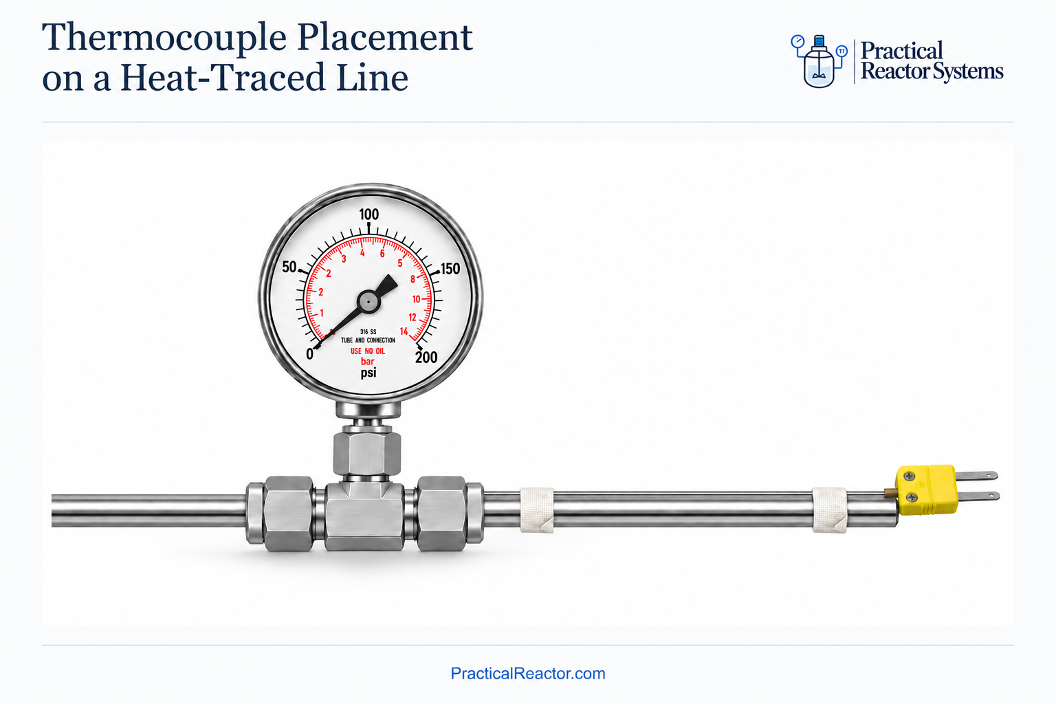
When heat tracing a reactor line, one of the most important decisions is where to place the control thermocouple. The controller measures temperature at one location, but the heated section may contain several components that warm up at different rates. How the heat tape is distributed across those components also affects whether the entire section reaches its intended temperature.
This article focuses on thermocouple placement and its relationship to heat-trace coverage. We’ll cover the specifics of heater selection and wrapping methods in a separate article, along with a separate discussion of redundancy and independent overtemperature protection.
Component Temperature Limits and Heating Response
Start by looking at what’s inside the heated section. Is it simply a length of 1/4-inch tubing, or does it also include valves, fittings, and a sample cylinder? Two things deserve particular attention: each component’s temperature limit and how quickly it responds to heating.
Consider a line with a small ball valve and a larger sample cylinder. For this example, assume the valve is rated to 148°C, the cylinder is rated to 371°C, and the control setpoint is 110°C. A setpoint below both ratings does not guarantee that every component will stay below its limit. The thermocouple’s location matters.
If you place the thermocouple on the sample cylinder, its larger thermal mass may cause it to warm up slowly. While the controller continues supplying heat, the smaller valve may heat up faster and exceed its temperature limit before the cylinder reaches the setpoint. Whether this happens depends on the heat input, wrapping, insulation, and heat losses, as well as thermal mass.
If you place the thermocouple on the valve, the opposite problem can occur. The valve reaches the setpoint and the controller reduces power, but the sample cylinder is still below the intended temperature. The controller may read 110°C even though part of the assembly remains substantially cooler.
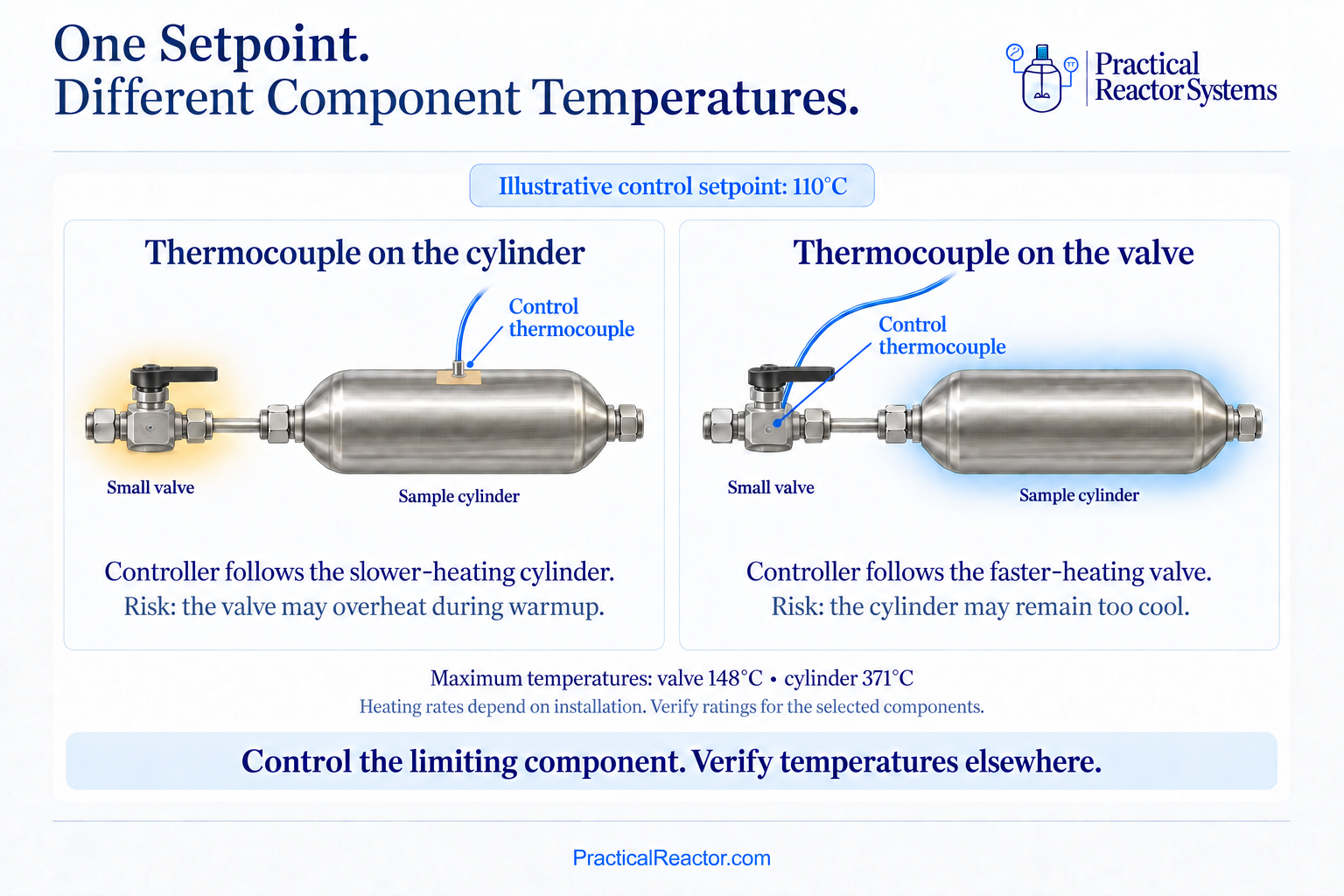
Comparison of thermocouple placement on the sample cylinder versus the valve at a 110°C setpoint, showing valve-overheating and cylinder-underheating risks.
Selecting the Control Thermocouple Location
In this situation, my starting point would generally be to place the control thermocouple on the faster-heating component with the lower temperature limit. In our example, that would be the valve. This makes the controller responsive to the component we are most concerned about overheating. However, placing the thermocouple correctly is only part of the setup. How the heat tape is distributed between the valve and cylinder also affects whether both components reach an acceptable temperature.
Heat-Trace Coverage and Heat Distribution
For example, if you concentrate too much heat tape on the valve and provide too little on the cylinder, the valve may reach the setpoint quickly and cause the controller to reduce power before the cylinder has warmed sufficiently. The thermocouple may be doing exactly what it should, but the heat is not being distributed where it is needed. The reverse is also possible. Even with appropriate coverage on the valve, too much heat input to the cylinder could cause it to exceed its intended temperature while the controller continues maintaining the valve at 110°C. A thermocouple on the valve cannot tell you whether the cylinder is too hot or too cold.
This is where understanding the output of the heat tape and how to apply it becomes important. The heater’s power per unit length, the amount applied to each component, its contact with the surface, and the insulation all influence how the assembly heats up. Simply running a length of heat tape along one side of the cylinder may not provide enough heat or distribute it adequately. Closely wrapping the entire cylinder may put more heat into it than needed. Neither arrangement should be assumed to work based on appearance alone, and the allowable spacing, bending, and overlap depend on the particular heater’s installation requirements.
Verifying Temperatures and Adjusting Coverage
Experience with similar assemblies can give you a starting point for how to distribute the heat tape, but the arrangement still needs to be checked. During initial testing, monitor how both the valve and cylinder respond through warmup and after temperatures stabilize, with the intended insulation installed. If an additional monitoring thermocouple is available, place it on the cylinder. If a permanent sensor is not available, a temporary surface thermocouple can help establish how the cylinder responds while the valve controls the heat. Remember that this is still a local measurement, so checking more than one location on the cylinder can help identify uneven heating.
Those measurements can guide adjustments to the heat-trace coverage. If the cylinder stays too cool, review the heat being supplied to it, the heater’s surface contact, and its heat losses. If it gets too hot, review whether too much heater output is concentrated there relative to the valve. Make any physical adjustments with the heater de-energized and the assembly cooled, then repeat the check. The goal is to keep both components within their required temperature ranges while controlling from the selected location.
Also, don’t assume a cooler cylinder only needs more time. Depending on heat input and heat losses, it may remain below the required temperature even after the system stabilizes. If suitable heat-trace coverage cannot keep both components within their required ranges on one control zone, separate heating zones may be needed. An additional monitoring thermocouple helps you understand this behavior, but it does not automatically provide independent overtemperature protection. We’ll discuss that distinction in the separate safety article.
Thermocouple Placement on Valves and Tubing
Now consider a simpler arrangement: a valve connected to 1/4-inch tubing, without a large sample cylinder. The difference in heating behavior may be smaller, but tubing diameter alone does not tell you whether the valve and tubing will track each other’s temperature. Valves can act as additional heat sinks and may require different heat-trace coverage than the surrounding tubing. If the valve is the limiting component, placing the thermocouple on the valve body is a reasonable starting point. A nearby tubing location may also work, provided measurements confirm that it represents the valve’s temperature during both warmup and steady operation.
Whichever location you choose, secure the sensing junction in reliable thermal contact with the surface you intend to measure, using an attachment method suitable for the operating temperature. Follow the heater and sensor manufacturers’ installation guidance. A convenient fitting nut is useful only if its temperature represents the component you need to control.
The practical lesson is to consider thermocouple placement and heat-trace coverage together. Choose the control location based on the components in the heated section, distribute the heat according to their needs, and verify how the assembly actually heats up. A stable controller reading tells you what is happening at the thermocouple. Measurements elsewhere help establish whether the rest of the line is reaching and staying within its intended temperature range.