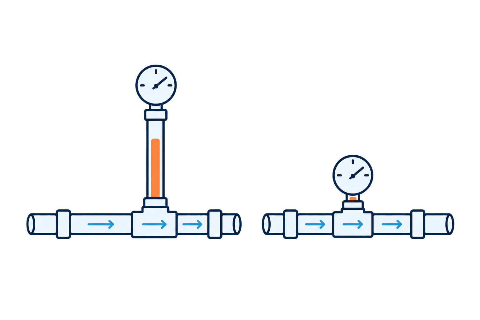
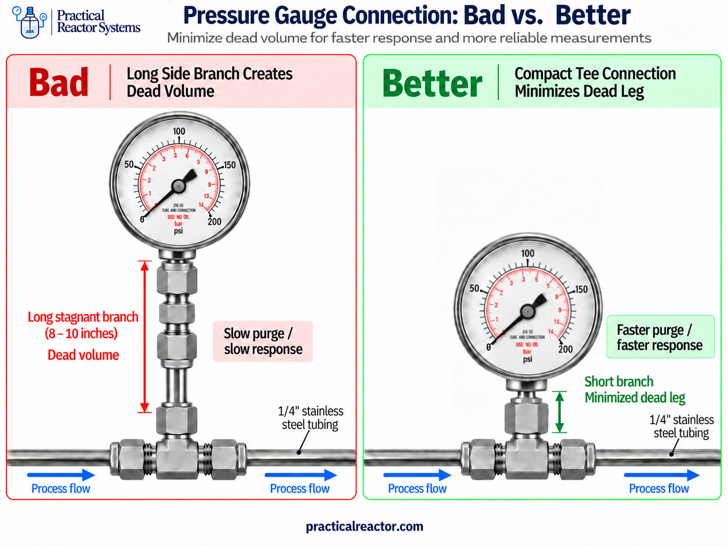
Dead volume is any part of a reactor system that the process flow doesn’t sweep through, and on a lab unit it’s worth designing out wherever you can. Dead legs, the branches that hold volume off the main flow path, are the biggest source. They take a long time to purge, they slow down every composition change, and on some services they can foul or plug.
The overall hold-up volume of the system matters too. Every extra foot of tubing between the feed, the reactor, and the analytical equipment adds delay to every condition change, for the life of the unit.
The examples here lean toward continuous units, where compositions change during a run and online analysis runs constantly. The same principles apply to batch and semi-batch reactors. Their sample lines, whether routed to online analysis or drawn manually, are hold-up volume too: a long sample line has to be purged before the sample represents what’s in the reactor. And instrument and relief branches can foul or plug on any unit.
I saw this firsthand on a unit I finished building, where instrument branches up to a foot long had us waiting one to two hours for each composition change to settle. I’ll come back to that example after covering why it happens.
Hold-Up Volume, Dead Volume, and Dead Legs
These three terms get used loosely, and it helps to keep them apart.
- Hold-up volume is the total internal volume between two points, such as feed manifold to reactor, or reactor outlet to GC. Every inch of tubing and every fitting, valve, and filter adds to it.
- Dead volume is the part of that hold-up the flow doesn’t sweep through. It fills and empties slowly, by diffusion and mixing, instead of being pushed out.
- A dead leg is the most common source of dead volume: a branch off the flow path that ends at something with no flow out of it. Gauges, transducers, relief devices, capped ports, and closed valves on a tee are all dead legs.
Instruments carry their own dead volume too. A Bourdon tube gauge has internal volume, and a transducer has a cavity in front of its diaphragm.
Purge Time in Dead Legs
Gas in a dead leg isn’t pushed out by the flow. It leaves mostly by diffusion, and diffusion is slow over long distances. The characteristic time scales with the square of the leg length:
t ≈ L² / D
Here L is the leg length and D is the diffusion coefficient for the gas pair. Three consequences follow.
- Length is punished twice. Double the leg and you roughly quadruple the purge time. A 12 inch leg isn’t three times worse than a 4 inch leg. It’s closer to nine times worse.
- Pressure makes it worse. Gas diffusivity falls roughly in proportion to pressure. At 10 bar, the same leg takes on the order of ten times longer to equilibrate than at 1 bar.
- Liquids are far worse. Liquid diffusivities run about 10,000 times lower than gases. A liquid dead leg effectively never flushes by diffusion. It only exchanges through turbulence and flow disturbances.
For scale, gas diffusivities at 1 atm are typically 0.1 to 0.2 cm²/s. A 30 cm (12 inch) leg gives L²/D of about 4,500 to 9,000 seconds, or roughly 1 to 2.5 hours. Treat that as an order of magnitude, not a prediction. Swirling flow at the mouth of a branch flushes the first couple of tube diameters quickly, which is why a short, close-coupled tee behaves far better than the formula suggests for a long one.
Tubing size changes how much stale gas a leg stores, not how fast it leaves. 1/4 inch tube with a 0.035 inch wall holds about 5 mL per foot. 1/8 inch tube holds roughly a seventh to a tenth of that, depending on wall. Smaller tube means less stale material bleeding into the main stream, but the time scale is still set by length.
Hold-Up Volume and Response Time
Dead legs are the worst offender, but swept volume matters too. Every extra foot of tubing between feed and reactor, or between reactor and analytical equipment, adds delay, cost, and panel space.
The delay is roughly the hold-up volume divided by the actual volumetric flow at line conditions. That second part catches people. Mass flow controllers are set in standard units, but gas at pressure is compressed. At 10 bar, 100 sccm is only about 10 mL/min moving through the line. A 50 mL hold-up then takes about 5 minutes per volume turnover, not 30 seconds.
Then there’s mixing. A step change in composition doesn’t arrive as a clean step. Fittings, filters, and the reactor itself smear it into a curve. For a well-mixed volume, getting within 1 percent of the new composition takes about 4.6 volume turnovers. Dead legs add a long tail on top of that, and the tail is what stretches a 10 minute switch into an hour.
On a unit built to run as many conditions per day as possible, that time is the product. Tubing you didn’t need is time you pay for on every condition change for the life of the unit.
Case Example: Long Instrument Branches
I took over a lab reactor unit that was roughly 70 to 75 percent built, to finish the build and the control system. The P&ID looked good. The tubing layout was the concern.
The pressure gauge, relief valve, and pressure transducer weren’t close-coupled to the main line. Each sat at the end of its own branch of 1/4 inch stainless tubing, some 10 to 12 inches long, teed off the process line with crosses. Process gas flowed straight through each cross while two stagnant branches hung off its sides.
The GC made the cost easy to see. We started runs with blanks at 90 percent nitrogen, then switched to the process feed. Nitrogen kept showing up in the analysis long after the main line should have cleared, and we waited one to two hours each time for the reading to settle at the new composition. Concentration changes behaved the same way.
None of that time produced data. It was the unit slowly emptying its own dead legs.
Dead Leg Location and Fouling Risk
Slow composition changes are the nuisance case. Whether a dead leg stays a nuisance depends on what’s in it and where it sits.
- Upstream of the reactor, stale feed bleeds into the reactor after a change and blurs the start of the new condition.
- Downstream of the reactor, stale product bleeds into the analytical equipment and contaminates the next data point.
- Reactive or unstable material is the real risk. Monomers can polymerize in a stagnant leg. Dissolved solids can precipitate. Condensables can drop out as liquid in a cool branch. Any of these can slowly plug the leg.
- Plugged branches fail silently. A relief device on a plugged branch can’t relieve. A transducer behind a plug reads a stale pressure, and any interlock using it is blind. The gauge still looks fine, because it’s showing the last pressure it saw.
That last point is what turns instrument dead legs from a throughput problem into a safety problem. A long, narrow inlet line to a relief valve also adds pressure drop on the relief path, which can make the valve chatter. If a relief path or a safety-critical measurement has to sit on a branch, keep it short, keep it clear of material that can foul it, and inspect it.
When a Branch Is Justified
One of the first people I built reactors with taught me a simple rule: don’t branch off the main flow path unless you have a specific reason to. That isn’t the same as “never branch.” Some reasons are good ones.
- Temperature. Transducers and gauges have maximum media temperature ratings. On a hot line, a standoff keeps the instrument within its rating. The tradeoff: a cool branch off a hot line is exactly where condensables drop out.
- Pulsation and vibration. A short standoff with a snubber can protect a gauge downstream of a pump.
- Access and layout. Sometimes an instrument has to sit where it can be read, reached, or removed without breaking into the main line.
When you need a standoff, make it only as long as the reason requires, and use smaller tubing where you can. Then write the reason down. If it isn’t documented, the next person can’t tell a deliberate design choice from a habit.
Design Practices for Minimizing Dead Volume
Most of this gets decided at layout, and much of it never shows on the P&ID. A P&ID draws a gauge on a tee the same way whether the branch is half an inch or a foot long. The unit I inherited had a clean P&ID. The problem was in the tubing.
- Close-couple instruments. Mount gauges, transducers, and relief devices right at the tee. Hygienic piping practice (ASME BPE) targets a branch no longer than about two tube diameters, which is a useful benchmark.
- Use a tee, not a cross, when one branch will do. Every extra branch is another dead leg.
- Put instruments on the flow path where you can. A transducer on the run of a flow-through tee is swept on every pass.
- Keep the main path short. Minimize tubing between the feed manifold and the reactor. On continuous units, also keep the run from the reactor outlet to the analytical equipment short, whether that’s a GC or an online FTIR.
- Size tubing to the flow. Oversized tube adds volume without adding capacity you need. 1/8 or 1/16 inch lines to the analytical equipment cut hold-up sharply.
- Pick low dead-volume components. Filters, valves, and fittings vary widely in internal volume. Zero dead volume fittings are standard on the analytical side for a reason.
- Orient branches deliberately. On gas lines, point instrument branches up so liquid drains back into the flow. On liquid lines, avoid high-point branches that trap gas.
- Review the build, not just the drawing. Walk the physical tubing, or a 3D layout, and ask of every branch: does flow go through this, and if not, why is it here?
For a unit that already has dead legs, pressure-swing purging helps. Pressurize, vent down, and repeat. Each cycle forces fresh gas into every leg and pulls old gas back out, so a few cycles can do what hours of flow-through purging can’t. A tracer step, like the nitrogen blank switched to feed, measures the unit’s real response time so you can plan runs around it.
Summary
Every branch off the main flow path is volume the flow can’t sweep. Its purge time grows with the square of its length, gets worse with pressure, and it can hide a plugged relief path or a blind transducer. Branch only when you have a reason, keep the branch as short as that reason allows, and check the tubing layout, not just the P&ID.