
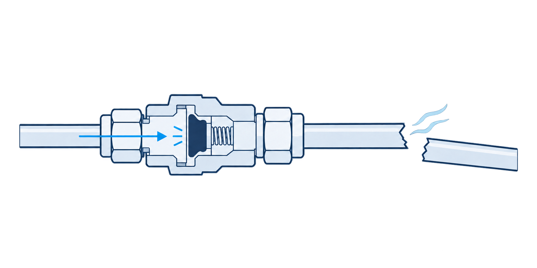
Excess flow valves, sometimes called velocity fuses, are common on gas panels and reactor feed lines. The basic idea is straightforward: if flow becomes abnormally high, the valve closes to limit the release. The mechanical designs discussed here do this without electrical power, control logic, or instrument air for the trip function.
Over my career working on lab and pilot-scale reactor systems, the three excess flow valves I used most were the Swagelok XS series, Parker FS190, and Malema M-VF. Although they serve a similar purpose, there are important differences in how they operate, what happens after they trip, and how they are put back into service. Those differences affected where we could use them and whether they met our site’s requirements for a safeguard.
When selecting one, I would start with two questions: will the failure you are trying to protect against produce enough flow to trip the valve, and what does the valve do once it has tripped? The nominal flow range is only part of that decision.
What an excess flow valve protects against
An excess flow valve responds to flow through the valve. It does not detect a leak directly, and it does not distinguish a broken line from a normal operation that happens to produce a high flow rate. A line rupture may trip it, but so may pressurizing an empty line during startup. A smaller leak can continue indefinitely if the flow remains below the trip point.
Even a completely broken line does not necessarily guarantee a trip. The available flow depends on the entire flow path, including the regulator, tubing, filter, needle valves, and any other restrictions. A long run of small tubing may limit flow enough that a break at the far end does not produce the flow needed to close the EFV.
That is why the selection needs to account for three things: the highest normal process flow, the valve’s trip range under the applicable conditions, and the flow the system can actually deliver through the failure being considered. The trip range needs to sit above normal operation while still allowing the valve to respond to that failure. If there is no workable separation between those conditions, a different setpoint alone may not solve the problem.
Operating principles and pressure dependence
These valves use the pressure differential associated with flow to actuate a mechanical closure. Swagelok uses a spring-loaded poppet, while Malema uses a piston held in its operating position by magnetic attraction. Parker lists a diaphragm, spring, orifice, and poppet in the FS190 assembly. The exact internal arrangement differs, but the practical point is the same: the valve’s response depends on the fluid and operating conditions, not just a flow number on an order sheet.
For gas service, inlet pressure can make a substantial difference to the trip flow expressed in standard units. Parker’s published data illustrates this clearly. The FS190’s A setting has a nominal flow limit of 4.8 standard liters per minute at 1,000 psig inlet pressure, compared with 0.4 standard liters per minute at 30 psig. Swagelok also publishes gas trip-range curves across inlet pressures. A valve should therefore be selected using the manufacturer’s data for the actual gas and conditions where it will operate.
The pressure that matters here is the pressure at the EFV. If it is installed directly on the high-pressure side of a cylinder system, it may experience a broad pressure range as the cylinder empties. If it is downstream of a regulator, its normal inlet pressure is the regulated pressure, with whatever variation occurs during operation. Those are different applications and should be evaluated that way.
Swagelok XS: automatic reset with a continuous bleed
The Swagelok XS uses a spring-loaded slotted poppet. During normal operation, the spring holds the poppet open. When flow reaches the trip range, the poppet moves to the seat and restricts the release. An intentional bleed path remains open, allowing pressure to equalize across the valve. Once it does, the spring returns the poppet to its open position automatically.
With the standard spring, Swagelok lists bleed flow as less than 1% of the flow rate in the trip range. The optional low- and medium-flow springs may allow a larger percentage. That residual flow is part of the design, so it needs to be considered when deciding whether the valve is suitable for an application.
The XS is available with different spring ranges and is not adjusted in the field like the Malema. It can operate in any orientation and fits into a tubing run much like a check valve, which makes installation straightforward.
We used it very rarely, and at my site it was not accepted for applications where the required safeguard was positive shutoff with deliberate reset. The bleed flow and automatic reopening did not meet those requirements. That does not mean the XS has no safety function. It means the function it provides has to match what the application requires.
Automatic reset also needs to be understood correctly. The valve reopens when pressure equalizes sufficiently; it does not verify that someone has found and repaired the problem. Whether pressure can equalize depends on the downstream condition. An open break may prevent equalization, while a smaller remaining leak may not.
Where we did find a use for it was in controlling a process bleed. Opening the bleed valve too far could disrupt the process. With an XS in the line, excessive bleed flow would trip the valve and reduce that flow. After the bleed valve was closed back down, pressure could equalize and the XS would reset. In that application, automatic reset was useful because the valve could return to service without a separate reset operation.
Parker FS190: gas service with deliberate reset
The Parker FS190 was another valve we used as a safeguard on a handful of systems, and it worked well in those applications. It is intended for gas service and uses a PCTFE seat, with Parker specifying bubble-tight internal shutoff. Six factory flow-limit settings are available, and the valve is not sensitive to mounting orientation.
The main distinction in day-to-day use was the reset control. The knob has two operating positions, Open (Reset) and Auto (Shutoff). We used the manual version, although Parker also offers a pneumatic reset option. Having a deliberate reset step fit the way we wanted to manage these systems after a trip.
The limitations that mattered most for our applications were gas-only service and its temperature rating. Parker lists an operating temperature range of -10°F to 150°F. The allowable inlet pressure range also depends on the flow-limit option, so that needs to be checked against the specific configuration being ordered.
Managing the reset position
The practical issue with the FS190 is that the Open position bypasses its excess-flow shutoff function. That position is useful when initially pressurizing a downstream line, but the knob can be left there. If it is, the valve is installed in the system without providing the protection expected from it.
An empty downstream line can draw enough flow to trip an EFV during initial startup or after maintenance. A cylinder change can create the same condition if the downstream section has been depressurized. With the Parker, our startup procedure needed to account for using the reset position and then returning the knob to Auto once pressurization was complete.
That return to Auto should be an explicit step in the applicable procedure. It is also something worth checking during a system walkdown. The valve’s position is part of confirming that the safeguard is available.
Malema M-VF: adjustable trip and multiple reset options
The Malema M-VF is the valve I used most, and it was generally my first choice for these applications. It uses magnetic attraction to hold a piston in its operating position. As flow increases, the pressure differential across the piston eventually overcomes that attraction and moves the piston to the seat.
It can be used with liquids or gases and offers several combinations of shutoff, reset, and setpoint adjustment. Those choices were useful because they allowed us to select a configuration that fit the application. The exact body, piston, seals, and reset arrangement still need to be checked for compatibility with the fluid and operating conditions.
Setting and verifying the trip point
I have used both factory-preset and field-adjustable versions. With the factory-preset option, the intended fluid, flow, and operating conditions are provided when ordering. With the adjustable version, the trip setting can be established in the system.
Malema’s published adjustment procedure has the user establish maximum flow, turn the adjusting screw clockwise until the valve trips, stop the flow, and then back the screw out one turn. That final step matters: the flow at which the valve initially tripped during adjustment should not be assumed to be the final trip point after the screw is backed out.
At our site, we designated a maximum allowable flow for the line and required the EFV to trip at or below it. For that type of requirement, completing the adjustment procedure is only part of the work. The final setting needs to be verified against the allowed flow under the applicable operating conditions. Simply setting it at a somewhat lower flow is not enough to establish what the finished setting will be.
Bleed and positive-shutoff configurations
The M-VF is available with either a bleed function or positive shutoff. The bleed version allows pressure equalization through the valve and can reset automatically. The positive-shutoff version uses a seal to stop the flow and requires pressure equalization through the selected reset arrangement.
For positive-shutoff applications, Malema offers several reset arrangements. These include an intrinsic reset with an internal bypass, versions that bleed to atmosphere or a sample container, and a standard arrangement that can be installed with an external equalization bypass. I have used both intrinsic reset and an external bypass, and both worked for our systems. The external loop was straightforward to build, although it added another valve and flow path that needed to be included in the operating procedure.
The reset options are not available in every connection size. Chemical compatibility also extends beyond the body material to the piston construction, seals, and any other wetted materials. Those details are worth checking before selecting a part number.
A useful distinction is that pressure equalization resets the Malema mechanism. It should not be described as a mechanically latched shutdown that can only reopen when a particular reset control is operated. The installed arrangement needs to provide the intended control over equalization and return to service.
Installation orientation
Malema recommends horizontal mounting. I would follow that recommendation and verify operation in the installed orientation. A calibration or functional check performed in a different orientation should not automatically be assumed to represent the installed valve.
Practical comparison
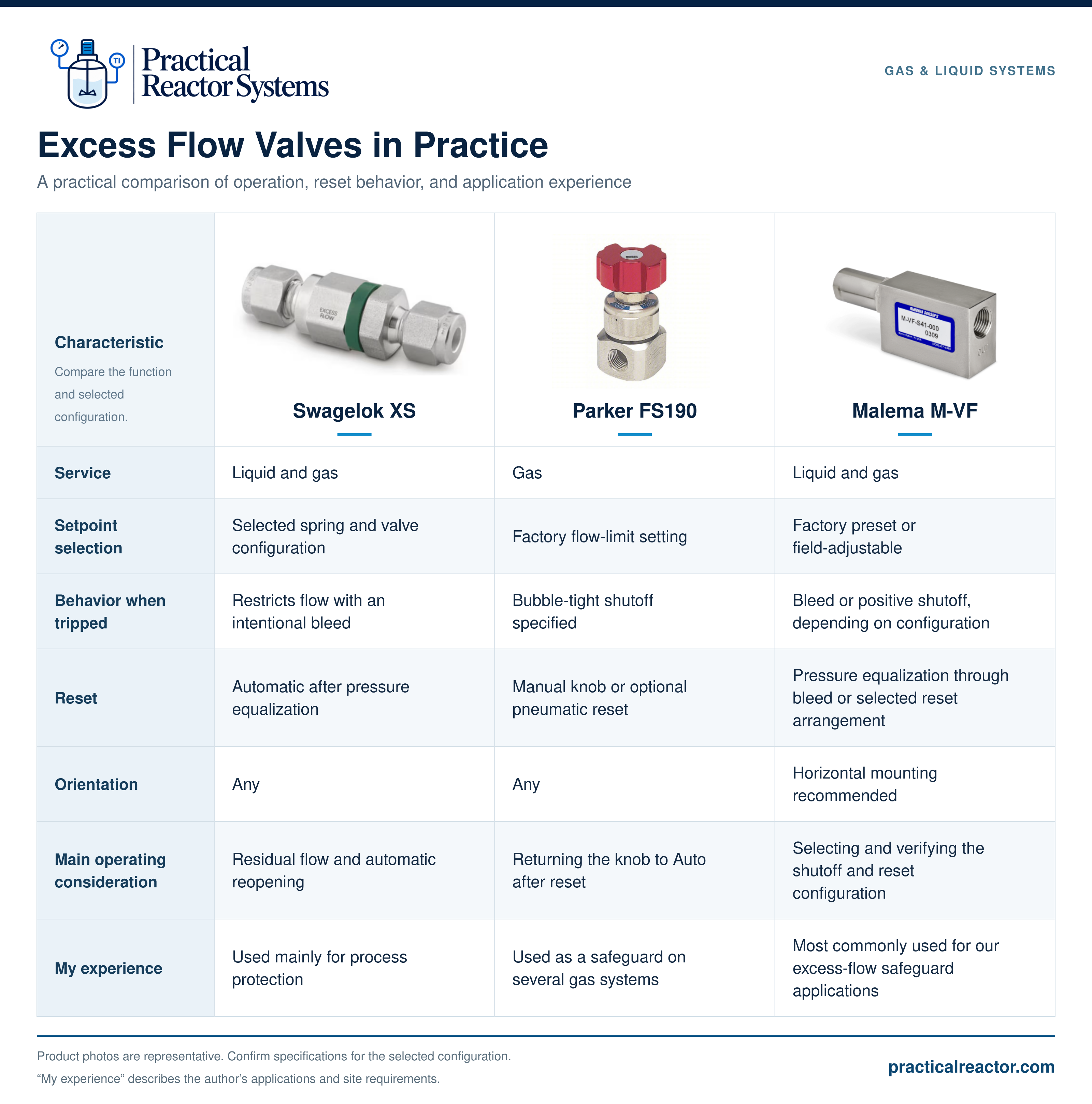
| Characteristic | Swagelok XS | Parker FS190 | Malema M-VF |
|---|---|---|---|
| Service | Liquid and gas | Gas | Liquid and gas |
| Setpoint selection | Selected spring and valve configuration | Factory flow-limit setting | Factory preset or field-adjustable |
| Behavior when tripped | Restricts flow with an intentional bleed | Bubble-tight shutoff specified | Bleed or positive shutoff, depending on configuration |
| Reset | Automatic after pressure equalization | Manual knob or optional pneumatic reset | Pressure equalization through bleed or selected reset arrangement |
| Orientation | Any | Any | Horizontal mounting recommended |
| Main operating consideration | Residual flow and automatic reopening | Returning the knob to Auto after reset | Selecting and verifying the shutoff and reset configuration |
| My experience | Used mainly for process protection | Used as a safeguard on several gas systems | Most commonly used for our excess-flow safeguard applications |
Selecting the trip range for the installed system
Our approach was to designate a maximum allowable flow for the line and select the EFV around that requirement. That gave us an upper limit, but it still had to be checked against normal operation and the failure we were trying to address.
The first check is normal process flow. The valve needs enough margin to remain open during intended operation, accounting for its trip tolerance and any normal transients. Otherwise, the system may trip repeatedly during operations that are supposed to be allowed.
The second check is the upper end of the trip range. Where a site requirement specifies a maximum allowable trip flow, the selected valve must meet that requirement across the relevant pressure, temperature, and fluid conditions, including the manufacturer’s tolerance. A nominal setpoint below the limit does not by itself establish that the full trip range is below it.
The third check is available failure flow. The system must be capable of producing enough flow through the EFV to reach its trip range during the failure being considered. This needs to account for restrictions both upstream and downstream of the valve. A bench check showing that the valve closes when supplied with unrestricted flow does not establish that it will close after a break at the end of the installed tubing run.
For gas service, perform those checks over the actual pressure range at the EFV. Include the lowest usable pressure, where available delivery flow may be reduced, as well as the higher-pressure conditions that can change the trip flow. If regulator failure is one of the scenarios the EFV is expected to address, evaluate that condition separately from normal regulated operation.
Installation and startup considerations
Upstream filtration
An upstream filter helps keep debris out of the moving mechanism and sealing surfaces. Malema specifically identifies particles interfering with piston travel as a concern. Debris can also prevent a valve from sealing properly after it trips.
The filter needs to be included in the flow evaluation. Its pressure drop, including the condition at which it is due for service, can affect the flow available to trip the EFV. Installing a filter and then ignoring it until the valve is tested misses part of the system’s behavior.
Pressure ratings and relief protection
The EFV and surrounding components need to be suitable for the pressures they can experience. On a regulated cylinder supply, that includes considering what happens if the regulator fails open. Where the downstream equipment cannot withstand the resulting pressure, the system needs appropriate overpressure protection.
On the panels we used, a relief connection upstream of the EFV allowed the relief path to remain available without passing through the EFV. That was part of the panel’s protection arrangement, rather than a universal installation rule for every excess flow valve. Relief capacity, discharge routing, set pressure, and the effect of isolation valves all need to be considered as part of that design.
Maximum pressure and temperature values should also be read together. For example, Swagelok’s XS catalog lists a pressure rating that decreases as temperature increases. The highest pressure and highest temperature in a product summary are not necessarily allowable at the same time.
Placement and coverage
An EFV can limit supply flow to a failure downstream of it. It does not protect the components upstream of its location, and it does not remove fluid already stored in downstream piping or equipment.
A typical arrangement we used placed the EFV downstream of the pressure regulator, gauges, a needle valve, vent and relief connections, and a filter. A check valve and an outlet block valve followed the EFV. The main release scenario we were addressing with the EFV was a break in the longer tubing run out to the point of use.
Our panels were located on an open gas pad with area classification and a deluge system. That setting was part of the overall hazard review, particularly for leaks on the cylinder side of the EFV. An enclosed installation would have different concerns about accumulation and ventilation. Outdoor placement also does not, by itself, establish that an upstream release is acceptable.
Moving an EFV closer to the source can extend the portion of the system downstream of it, but it changes the pressure and flow conditions used for selection. A restrictive flow orifice at the source is another option for limiting supply to downstream failures, although its interaction with any EFV needs to be checked.
Startup and reset
Startup procedures should account for the flow needed to pressurize empty piping. Where the arrangement allows it, gradually opening an upstream needle valve can reduce the initial surge. That does not eliminate the need to verify the EFV’s operating state before starting the process.
After an unexpected trip, identify and correct the cause before restoring flow. The reset procedure should then match the actual valve and piping arrangement. For the Malema installations we used, an equalization path was part of the reset design. Depending on the arrangement, equalization may be achieved through a bypass or an approved depressurization procedure. The destination of any vented gas matters, especially for flammable or toxic service.
That pressure-equalization discussion should not be treated as a universal reset instruction for every EFV. The Parker has its own reset control, and the Malema procedure varies with the reset option. Any bypass opened during reset needs to be returned to its normal position before the system resumes operation.
The downstream check valve serves a separate purpose. An excess flow valve selected for forward-flow protection should not also be assumed to provide the backflow protection needed by the process.
Maintenance and functional verification
At the R&D site where I worked, EFVs used as safeguards were included in the preventive maintenance program along with devices such as relief valves and vapor monitors. Each valve was tagged and entered into a system that identified when it was due for inspection or service. The frequency came from the site’s requirements.
The useful check is whether the valve still performs the function it was installed to provide. Depending on the valve and application, that includes verifying the trip flow, confirming the expected reset behavior, and checking shutoff performance after a trip. A positive-shutoff valve that moves to the closed position but leaks through its seat has not necessarily met the requirement.
The upstream filter should be inspected or serviced as part of the maintenance plan as well. Its condition can affect both valve cleanliness and available flow. Replacement frequency should reflect the service and maintenance requirements, rather than assuming the filter and EFV always need replacement together.
Functional verification should use a controlled test arrangement appropriate for the fluid and hazard. The purpose is to confirm the safeguard’s behavior without creating the uncontrolled release it is intended to address. After testing, confirm that reset valves, bypasses, and operating controls have been returned to their required positions.
Excess flow valve or restrictive flow orifice?
A restrictive flow orifice is a common alternative when the requirement is to limit release rate. It has no moving shutoff mechanism and no reset operation. In many of the systems I worked on, an appropriately selected orifice could have been used instead of an EFV.
The main difference is that an orifice continues to pass flow. It limits the rate according to its size and the upstream and downstream conditions, but it does not isolate the source after a line breaks. Whether that is acceptable depends on the gas, the location, the potential duration of release, and the site’s requirements. Its sizing also needs to account for the highest credible driving pressure, rather than only normal regulated operation.
An orifice also imposes a restriction during normal operation. An EFV has its own pressure drop, which needs to be checked, but it can provide shutoff after the trip range is reached. If the application requires positive shutoff, an orifice alone does not provide that function.
The two devices can be used together, but their interaction matters. If an upstream orifice limits flow below the EFV’s trip range, a downstream break may never trip the valve. In that situation, the orifice may still limit the release, but the EFV cannot be assumed to provide the additional shutoff. Both devices need to be evaluated as part of the same flow path.
Choosing the valve for the application
The Malema M-VF was generally my preferred choice because it worked with liquids and gases and gave us flexibility in setting the trip point and choosing the reset arrangement. The Parker FS190 also worked well in the gas systems where we used it, provided its reset position was managed correctly. The Swagelok XS had a useful role where its bleed and automatic reset matched the intended function, even though it did not meet our site’s requirements for positive shutoff with deliberate reset.
Whichever valve is selected, the part number is only one piece of the design. The installed system needs to produce enough flow to trip it during the failure being considered, keep it within its operating limits, and allow it to be tested and returned to service correctly. Those checks are what turn an EFV shown on a P&ID into a safeguard that performs the intended job.