The furnace is one of the most important components to get right in a lab-scale reactor system. A furnace poorly matched to the reactor makes temperature control difficult, increases heat-up time, creates unwanted temperature gradients, and can affect the chemistry taking place inside the reactor.
This article focuses on split-tube furnaces used with continuous-flow, fixed-bed or plug-flow style reactors, where a tubular reactor containing a catalyst bed passes through the furnace. Most of the same principles apply to other configurations, but split-tube furnaces are what I have used most often for this type of reactor.
At first glance, choosing one seems simple: determine the reactor diameter, pick a furnace that reaches the required temperature, and make sure it is long enough to contain the catalyst bed.
In practice, the furnace needs to do several things:
- Bring the incoming process stream to reaction temperature.
- Maintain the catalyst bed at the desired temperature.
- Provide enough power to compensate for heat losses and reaction heat effects.
- Produce an acceptable temperature profile through the reactor.
- Allow the products to leave the reaction zone without unnecessary additional thermal exposure.
Getting those things right starts with the catalyst bed.
Start With the Catalyst Bed
Start by determining the approximate size and location of the catalyst bed. The amount of catalyst required is driven by the chemistry and the desired operating conditions: catalyst loading, space velocity, residence time, flow rate, conversion, and so on.
Once you know roughly how long the bed will be, you can determine how much heated length you need. A six-inch catalyst bed does not mean you need a six-inch furnace. You may also need furnace length for:
- Preheating the incoming process stream.
- Creating a uniform-temperature region around the catalyst bed.
- Allowing for future increases in catalyst loading.
- Controlling the temperature immediately downstream of the bed.
There is another important consideration here: the isothermal region of a furnace zone is not necessarily centered perfectly within that zone.
It is easy to assume the middle of a heating zone is also the most uniform part of the temperature profile. In my experience, that is not a safe assumption. You find out where the isothermal region actually is by profiling the furnace.
That typically means placing a thermocouple inside a representative reactor tube and measuring temperature at different axial positions through the furnace under operating conditions. The profile shows you where the temperature is relatively flat, where the gradients begin, and where the catalyst bed should be positioned.
Profiling the furnace isn’t something you can do before purchasing a new one. However, once the furnace is installed, profiling is a critical step. It can also be extremely useful when deciding whether an existing furnace is suitable for a particular reactor or application.
I’ll keep the discussion brief here, because furnace profiling is a topic that deserves a much deeper explanation. There are also additional considerations, such as whether to use a thermowell or a multi-point temperature probe when the reactor diameter allows for it. I’ll cover those topics in more detail in future articles.
Decide Where the Process Will Be Preheated
The next question is whether the furnace will also preheat the process stream. In many lab-scale gas-phase systems this is a practical approach. The incoming gas enters the reactor tube above the catalyst bed and is heated as it travels through the first section of the furnace. Ideally, the process stream is already at or very near reaction temperature when it reaches the catalyst.
The furnace temperature and the process temperature are not necessarily the same thing. If the gas enters the furnace at 25°C and the reaction takes place at 400°C, setting the first furnace zone to 400°C does not guarantee that the gas will be at 400°C by the time it reaches the catalyst.
Heat has to move from the heating elements to the reactor wall, then from the reactor wall into the flowing process stream. How quickly that happens depends on:
- Gas flow rate.
- Gas heat capacity.
- Reactor diameter and wall thickness.
- Available preheat length.
- Furnace temperature.
- Heat-transfer characteristics inside the reactor.
The faster the flow and the shorter the preheat section, the less time the process has to approach the furnace temperature. This is one reason multiple furnace zones can be so useful.
Furnace Length Matters More Than You Might Expect
The total heated length of the furnace has a major effect on how the reactor performs. You need enough length to heat the catalyst bed, but you also need to think about what happens immediately before and after the reaction.
The downstream side is particularly important for chemistries where the products can continue reacting thermally after leaving the catalyst. If a product can crack, decompose, polymerize, isomerize, or undergo another undesirable thermal reaction at high temperature, you may want to decrease its temperature as quickly as practical after it exits the bed. A long hot section downstream of the catalyst works against you.
In that situation, I would rather have the catalyst bed end relatively close to the end of the heated region and then intentionally transition into a cooler section of reactor. For especially temperature-sensitive products, leaving the furnace may not cool the stream fast enough, and some type of active cooling or quench may be necessary.
Furnace length should be based on the entire desired reactor temperature profile, not simply the length of the catalyst bed.
How Many Furnace Zones Do You Need?
Single-zone furnaces work perfectly well for many reactor systems. But I have found multiple zones worth the additional cost when I want good control over the temperature profile through a continuous-flow reactor.
For a fairly typical lab reactor, I particularly like a three-zone furnace. One possible configuration:
Zone 1: Preheat. The reactor enters the furnace and the incoming process stream is heated toward reaction temperature.
Zone 2: Reaction. The primary catalyst bed begins near the entrance to this zone, after the process has had sufficient preheat length, and the zone is controlled near the desired reaction temperature.
Zone 3: Reaction extension or transition. This zone provides flexibility. It can be operated at reaction temperature if the catalyst bed needs to be longer, or at a lower temperature to begin decreasing the temperature of the products leaving the catalyst. Immediately downstream of the furnace, additional cooling can be added if the chemistry requires rapid quenching.
That flexibility becomes valuable when you start changing experiments. Maybe the original experiment used 10 mL of catalyst but the next project needs 25 mL. With a multi-zone furnace, you may be able to extend the bed farther into the next zone rather than redesigning the entire system.
Multiple zones also let you intentionally shape the axial temperature profile rather than accepting whatever profile a single heating zone produces. The exact dimensions will depend on catalyst volume, reactor diameter, flow rate, reaction temperature, and chemistry, but this arrangement provides a great deal of experimental flexibility without making the system unnecessarily complicated.
Watch the Temperature Difference Between Zones
The zones of a multi-zone furnace are not thermally isolated from each other. Heat conducts through the furnace insulation, reactor tube, internal components, and surrounding structure, and radiation moves heat between adjacent hot regions. You will always have some temperature transition between zones.
If Zone 1 is set to 250°C and Zone 2 is set to 450°C, the temperature does not suddenly jump 200°C at the boundary between them. There will be a gradient. That is not necessarily a problem, but you need to account for it.
You can also run into a situation where the furnace zones appear to be at the correct temperatures while the process stream itself has not had enough time to reach reaction temperature before entering the catalyst bed. One solution is to operate the upstream zone at a somewhat higher temperature so that the process reaches the desired temperature at the catalyst entrance.
The important measurement is the actual process temperature, not the furnace controller setpoint. That is why thermocouple placement matters so much when commissioning the reactor.
Calculate the Required Heat Duty
After settling the basic furnace geometry, determine how much heating power is required.
For the process stream, a good starting point is:
Q̇ = ṁ × Cp × ΔT
where:
- Q̇ = required heat-transfer rate, or thermal power
- ṁ = mass flow rate
- Cp = heat capacity
- ΔT = temperature increase
When SI units are used, the result is in watts. If heat capacity changes significantly over the temperature range, using an average or integrated heat capacity will give a better estimate.
But heating the process stream is only part of the furnace duty. You also need to consider:
- Heat loss through the furnace and reactor ends.
- Heat of reaction.
- Heat required to warm the reactor tube.
- Heat required to warm the catalyst.
- Heat required to warm thermowells, fittings, inserts, and other internal components.
The heat of reaction can be particularly important.
For an endothermic reaction, the catalyst bed removes heat from the surrounding system, and the furnace needs enough available power to maintain the desired bed temperature while the reaction is occurring.
An exothermic reaction creates the opposite problem. The reaction itself generates heat, and the catalyst temperature can rise above the surrounding furnace temperature. In that situation, furnace sizing is no longer only about supplying enough heat. You also need to consider whether the system can remove the heat being generated and whether your thermocouple arrangement will detect a temperature excursion inside the catalyst bed.
For example, suppose the process stream requires 200 W of heating at your maximum flow rate, the reaction requires another 100 W, and the furnace and reactor lose approximately 400 W to the surroundings:
- Process heating = 200 W
- Heat of reaction = 100 W
- Furnace and reactor heat losses = 400 W
- Total steady-state heat duty = 700 W
That does not mean I would specify a 700 W furnace. You still want additional capacity so the furnace is not operating continuously at 100% output and so the reactor can heat from room temperature to operating temperature in a reasonable amount of time.
This is where it is useful to separate steady-state heat duty from startup heat requirements.
Heating the continuously flowing process stream, compensating for heat losses, and accounting for the heat of reaction determine the steady-state heat duty. Heating the reactor tube, catalyst, thermowells, and other thermal mass primarily affects startup and how quickly the system can move between operating temperatures.
You can therefore have a small gas-phase reactor that requires relatively little power once it reaches steady state but still benefits from substantially more installed furnace power to reach operating temperature in a reasonable amount of time.
Don’t Undersize, or Blindly Oversize, the Furnace Power
An underpowered furnace is easy to recognize. It may take a very long time to reach temperature, or the controller output may sit near 100% while the furnace struggles to maintain setpoint under actual process conditions.
But specifying the highest-powered furnace available is not always the best solution either.
I learned this firsthand on a reactor where I had oversized the available furnace power. The system worked, and with appropriate tuning we could control it, but it became particularly challenging when we ran temperature studies where the reactor was ramped sequentially to several different setpoints.
When moving from one setpoint to the next, the furnace could add heat very quickly. By the time the control system responded to the changing temperature, enough energy could already be in the furnace and reactor assembly to carry the temperature beyond the desired setpoint.
That makes a study such as 300°C → 325°C → 350°C → 375°C → 400°C more difficult than it needs to be. Instead of smoothly reaching each temperature and stabilizing, you spend additional time dealing with overshoot, waiting for the reactor to settle, or adjusting control parameters to get acceptable performance across the full temperature range.
A properly tuned PID controller, appropriate power modulation, good thermocouple placement, and a well-designed furnace can control a considerable amount of installed power, so excess power is not automatically a problem. But there is a point where additional heater capacity stops being useful and begins making the system unnecessarily difficult to control.
The goal should be enough power to reach operating temperature in a reasonable amount of time and maintain temperature under load, while still matching the heater response reasonably well to the thermal mass of the reactor system.
For reactors that will routinely perform temperature-ramp studies, this becomes particularly important.
Furnace Bore Diameter Also Matters
Consider the internal diameter of the furnace relative to the outside diameter of the reactor tube. A very large bore may be convenient because it can accommodate many different reactor sizes, but that flexibility comes with tradeoffs.
When the reactor tube is relatively small compared with the furnace bore, thermal coupling between the furnace and reactor can become less efficient and the reactor may respond more slowly to changes in furnace temperature.
The exact effect depends on the furnace design and operating temperature. At higher temperatures, radiant heat transfer becomes increasingly important, while at lower temperatures convection and conduction play a larger relative role.
In some applications, heat-transfer sleeves or inserts can be used around a smaller reactor tube to improve thermal coupling or reduce the amount of open space in the furnace.
I have used high-conductivity metal inserts successfully for this purpose, but material selection deserves careful attention. Temperature rating, oxidation, thermal expansion, interaction with the reactor tube, and mechanical properties at operating temperature all matter.
I would not select an insert material simply because it has high thermal conductivity at room temperature.
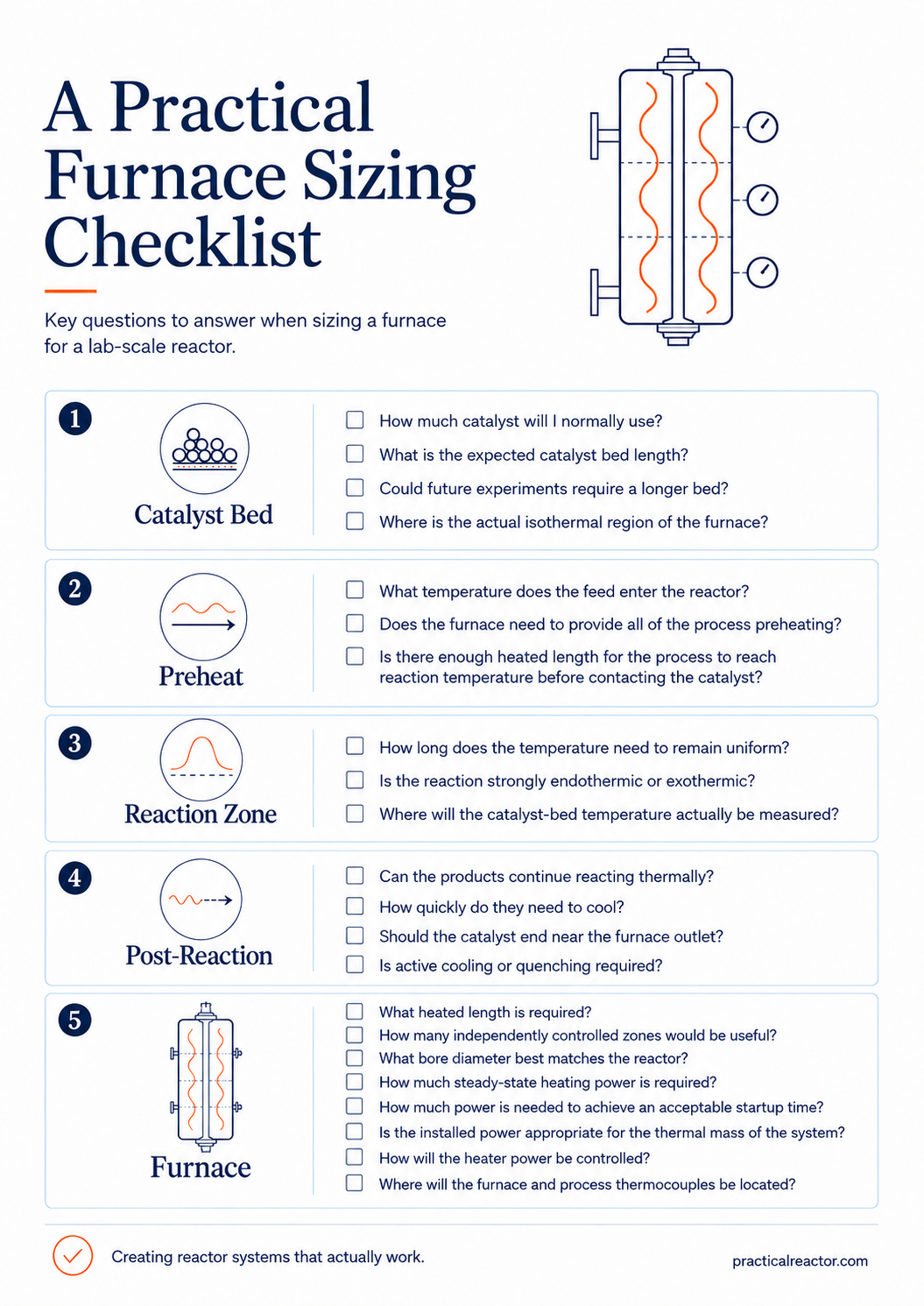
A Practical Furnace Sizing Checklist
Before selecting a furnace for a lab-scale reactor, I would work through the questions in the checklist below.
The Bottom Line
There isn’t one furnace size that is correct for every lab-scale reactor. The right furnace is the one that produces the temperature profile the experiment actually requires.
Start with the catalyst bed and work outward. Determine how much preheat length is necessary, where the reaction should occur, and how quickly the products need to cool afterward. Then determine the required heating duty, furnace power, bore diameter, and number of zones.
For many continuous-flow lab reactors, I have found a three-zone split-tube furnace to be an excellent compromise between simplicity and flexibility: enough control to preheat the process, maintain the catalyst bed, and adjust the downstream temperature profile as the experimental program changes.
Don’t design around the furnace setpoint.
Design around the temperature the process and catalyst actually experience.